WARNING: Unless you REALLY know what you’re doing, DON’T attempt fixing your Playstation power supply! The power board contains large capacitors which may deliver a deadly shock, also when the device is unplugged!
Short story:
– Playstation 2 Fat model no. SCPH-50004, input 240V
– Power supply module not delivering 12V to the motherboard. It was delivering 0V
– Went on taking voltage measurements at different points on the board, which sometimes triggered a discharge towards the negative, temporarily fixing the issue
– One capacitor turned out having a really large ESR and a large voltage loss
– Replacing this bad capacitor permanently fixed the issue
Long story:
Last Saturday while strolling through the flea market, some fairly looking console caught my eye. It was a fat PS2 with no warranty sticker. The seller was confident about it running just fine. He was arguing “my kids just paid 1500 RON (about 300 EUR) for a new console” while i was replying “yeah, that doesn’t mean this one’s working” :> I ended paying 30 RON (about 6 EUR) which makes it a true bargain! Of course I hoped it was working :))
At home, the first test and the console doesn’t power up! So i went disassembling it, dusting all components, case, cd-bay area. Isopropyl Alcohol is a great PCB cleaner, but don’t use it on plastic/rubber. There was a missing ribbon cable – connecting the controller unit to the motherboard and also, a cable connecting the cooler to its power supply. Interestingly the cooler fan was still in place.
Both missing parts can be bought online. That holds true for the power supply module, but attempting fixing it is more interesting
Things I tried:
– Went online looking for a power block schematic. Couldn’t find anything for the SCPH-50004 model, however there are fan-made schematics for other models.
– This is the best digest of schematics all of which seem to match the PS2 Power Source
– Also, note this schematic for the 90002

– None of the above schematics seemed to fully match my board
-
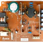
- SCPH-50004 Power Supply Unit
-
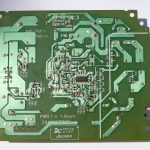
- SCPH-50004 Power Supply Unit – verso
– 0V at CN2 so I started following where we loose power. The C1 condenser was getting DC as it was past the bridge rectifier, and its voltage was 300V
– Same voltage at primary side of transformer T1 at both pins 1 and 3 and at first this looked ok
– Later on, while probing Voltage with the negative probe at C1 negative pin, and the positive probe at different points on the board, sometimes, a discharge was happening and the power supply started delivering 11.9V at CN2
– The conditions for the discharge were never identical, but somewhere in the same area. One example was probing with the voltmeter the diode D1B cathode and C1 negative pin, right after which the circuit started working normally. That’s when transformer T1 pin 1 was still displaying 300V where pin 3 was displaying a variable voltage of 0V, 12V, 2V, 1V, 0V, 17V, 0V, 20V, etc. This looks like a capacitor not doing the job
– Instead of looking at ceramic capacitors which rarely fail, I went considering the electrolytic capacitors: C20 and C3. For that I employed my ESR meter, hoping to tell which was bad before any desoldering
ESR metering:
– As the capacitance goes down the ESR goes up
Faulty C3 tested off board
- – for the C20 capacitor
- in circuit reading 89.79µF Vloss 7.4% ESR 1.5Ω
- the replacement was 23.90µF Vloss 0.9% ESR 2.6Ω
- off board it measured 22.49µF Vloss 1.2% ESR 0.65Ω
- So this was a good capacitor! Since it was off the board I went of replacing it anyways
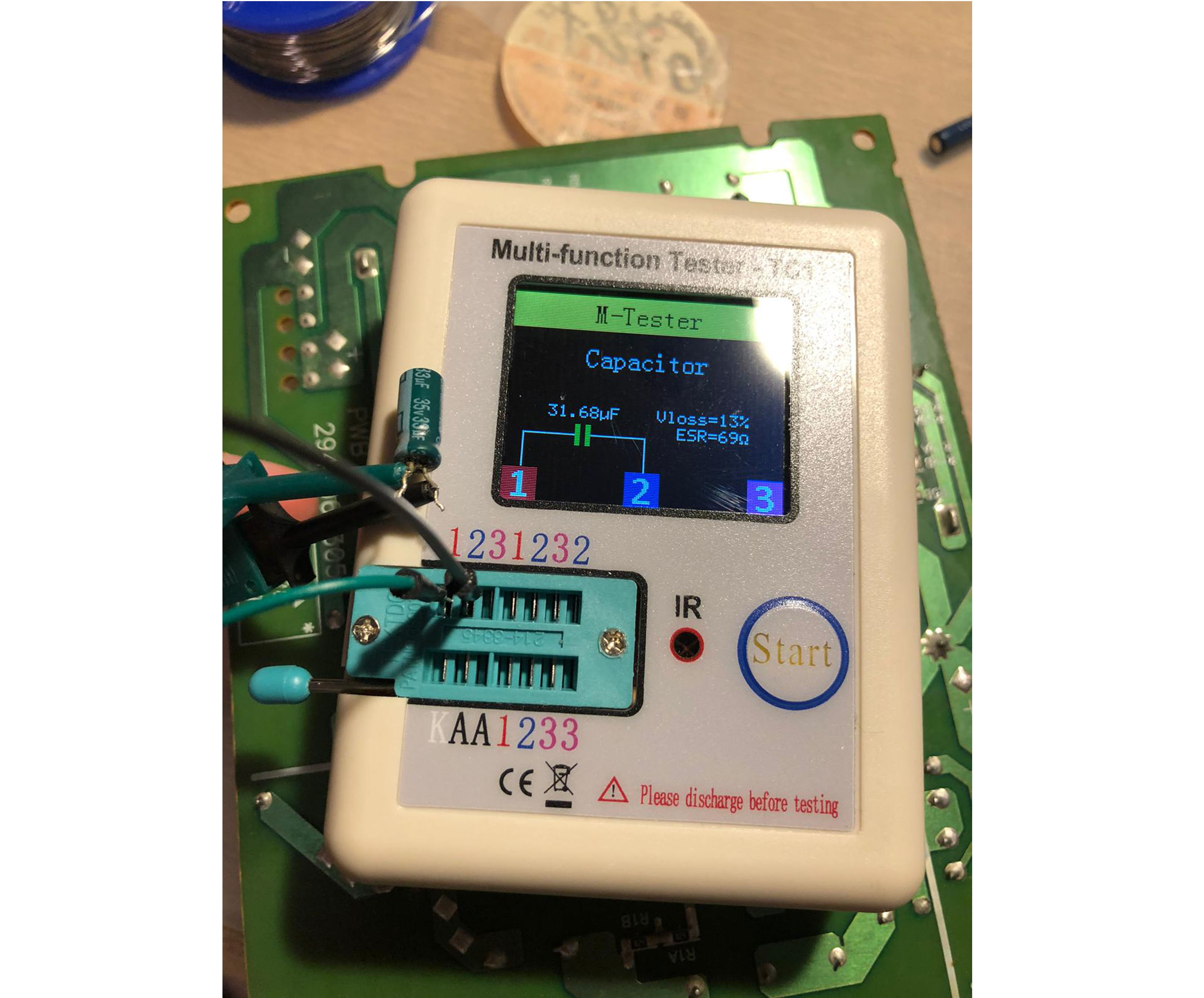
- – for the C3 capacitor
- in circuit reading 133.3µF Vloss 15% ESR 35Ω
- the replacement was 35.91µF Vloss 1.4% ESR 2.1Ω
- off board was reading 31.68µF Vloss 13% ESR 69Ω
- Given the abnormally high ESR not to mention the Voltage Loss, this is a faulty capacitor that needs replacement
Problem solved:

PS2 Power Source now delivering 12V to the motherboard
List of identified parts:
– Note, list is compiled based on original components in my SCPH-50004
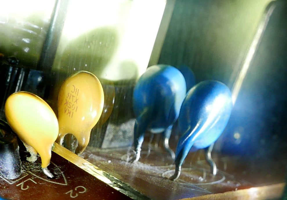
– C2, ceramic capacitor, BC X7R 102K 1KV, note the X7R class of -55º to 125º, and the K capacitor tolerance of 10%
– C3, capacitor, 33µF 35V
– IC2, optocoupler, PC123
– C20, capacitor, 22µF 50V 105º
– C21, ceramic capacitor, X7R 471K 1KV, that’s a 470pF 1000V with capacitor tolerance of 10%
– C22, ceramic capacitor, X7R 471K 1KV
– ZD2, zenner diode, 15V
– ZD3, zenner diode, 18V
– NTC1, thermistor, SCK 103 330
– Q1, dual Schottky diode, MBR20H100CTG
Useful links: